
Introduction
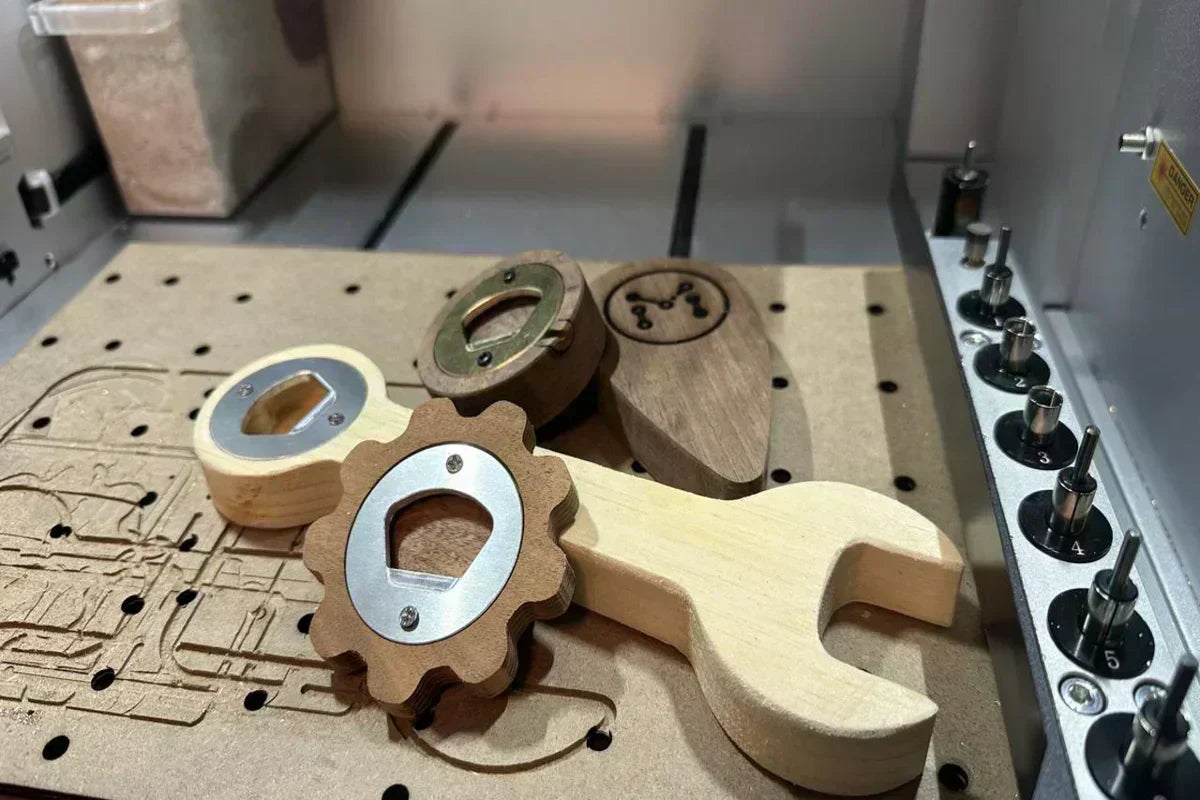
CNC machines can make a lot of different things, and versatile machines like the Carvera and Carvera Air can machine parts out of a range of materials too. To celebrate the summer season, we've created a number of projects to support enjoying the warm weather, starting with creating custom bottle openers!
Project Overview
This project includes two components:
- Wooden Handle
- Aluminum Cap
All designs and detailed video tutorials can be found here on our wiki site.
1. Wooden Handle
The first part of the bottle opener is the handle. We chose to use a hardwood for this part, though you could customize your design to machine this handle out of woods, plastics, or metals too! This part has also been shared in 2D and 3D file types on our wiki linked above.
The 3D file can be chosen to easily prepare this part using Makera CAM through 3D toolpath operations. But if you want to customize your handle shape with other vectors or imported images, the 2D profile is a better option to easily customize the design right in Makera CAM.
Resources Needed for the Handle Part
• We used the Carvera, but the Carvera Air would work well for this kind of project too.
• For stock, we used a piece of hardwood (Walnut) that is 130 mm x 80 mm x 20 mm in LxWxH.
• And for bits, we used a 3.175 mm x 25 mm single flute endmill.
Preparing the Tool Paths
To create this part, there are four tool paths needed to machine the different details in the design. And while you could use a few different tools, we've designed this part so each tool path can be completed with the same bit.
-
3D Pocket – Cap Opening

• Select the larger circular face in the opening of the handle, and the depth will be calculated automatically
• For the bit, choose the 3.175mm x 12mm Endmill with parameters to match your stock
• For Step Downs, enable stepdown based on your stock
• Consider adjusting your Tool Number to match the slot the tool is loaded in for the Carvera's Automatic Tool Changer
• Offset for Path Strategy, and Outside Boundary for Tool Containment
• And if you're using metal, enable Ramping, but this wouldn't be needed for wood
-
3D Pocket – Lower Pocket

• Next, choose the face at the base of the cap pocket, the machining depth will be calculated automatically
• For the bit, choose the 3.175mm x 25mm Endmill with parameters to match your stock
• For Step Downs, enable stepdown based on your stock
• Consider adjusting your Tool Number to match the slot the tool is loaded in for the Carvera's Automatic Tool Changer
• Offset for Path Strategy, and Outside Boundary for Tool Containment
-
3D Drilling – Pilot Holes

• Hold shift, and select the two holes
• For the bit, you could choose to use a drill, or instead perform the drilling operation using the same 3.175mm x 25mm Endmill with parameters to match your stock
• Consider adjusting your Tool Number accordingly
• Enable Fixed Z Height Retract at 1 mm
-
3D Contour – Cutting the Outer Profile

• Select the model, and Generate Contours around the selected Object
• Select the outer profile as your Generated Contour, the end depth will be calculated automatically
• Set an End Depth Offset of 0.1mm to ensure we cut all the way through the part
• For the bit, choose the 3.175mm x 25mm Endmill with parameters to match your stock
• For Step Downs, enable a stepdown depth based on your stock
• Consider adjusting your Tool Number accordingly
• For Position, choose Outside
• Lastly, enable Tabs and create custom tabs that are either rectangle or triangle shaped, and approximated 10 mm in width, and 3 mm in height. Place at least 2 tabs around the perimeter of your design.
And again, we show how to adjust all of these settings in greater detail in our guiding tutorial video linked above.
Manufacturing the Handle
To manufacture this project, start by loading your stock onto a piece of waste board and securing it using the corner clamps and top clamps included in our tool kit. We can then load the G-code files created in Makera CAM to our CNC through the Makera Controller App.
We want to enable Scan Margin to check the position of our project, and Auto Z Probe to measure the height of our stock automatically. If you are using a rough-cut piece of wood, consider using Auto Leveling to measure the height across your stock.
Once manufacturing is complete, carefully remove the part and cut away the tabs. You can use sandpaper to clean up the edges. And consider using an oil or varnish to seal this part and bring out the finish!
2. Aluminum Cap
The second part of the bottle opener is the opener part which removes the cap of the bottle. We chose to use aluminum for this part, though you could use a range of metals like brass or copper instead.
Resources Needed for the Cap Part
• We used the Carvera, but the Carvera Air would work well for this kind of project too.
• For stock, we used a piece of aluminum that is 100 mm x 100 mm x 3 mm (L×W×H).
• And for bits, we used a 3.175 mm × 12 mm single flute endmill and a chamfering bit for metal.
Preparing the Tool Paths
To create this part, there are five tool paths needed to machine the different details in the design.
-
3D Pocket – Opener Lip

• Select the face of the recessed pocket, the depth will be calculated automatically
• For the bit, choose the 3.175mm × 12mm Endmill with parameters to match your stock
• For Step Downs, enable stepdown based on your stock
• Consider adjusting your Tool Number to match the slot in the Carvera's Automatic Tool Changer
• Parallel for Path Strategy, and Outside Boundary for Tool Containment
• And enable Ramping with a distance of 10 mm, a fixed angle of 3 degrees, and a height of 1 mm
-
3D Contour – Holes

• Next, Select the bottom face and Generate Contours around the selected Face
• Choose the contours for the three holes at the base of the cap pocket, the machinnig depth will be calculated automatically
• Set an End Depth Offset of 0.1mm to ensure we cut all the way through the part
• For the bit, choose the 3.175mm x 12mm Endmill with parameters to match your stock
• For Step Downs, enable stepdown based on your stock
• Consider adjusting your Tool Number
• Inside for Strategy
• Enable Ramping with a distance of 10 mm, a fixed angle of 3 degrees, and a height of 1 mm
• Lastly, enable Tabs and create custom tabs that are either rectangle or triangle shaped, and approximated 5 mm in width, and 3 mm in height. Place 1 tab to hold the larger piece of metal in the center of the part
-
3D Contour – Cutting the Outer Profile

• Select the model, and Generate Contours around the selected Object
• Select the outer profile as your Generated Countour
• For the bit, choose the 3.175mm x 12mm Endmill with parameters to match your stock
• For Step Downs, enable a stepdown depth based on your stock
• Consider adjusting your Tool Number accordingly
• For Position, choose Outside
• Enable Ramping with a distance of 10 mm, a fixed angle of 3 degrees, and a height of 1 mm
• Lastly, enable Tabs and create custom tabs that are either rectangle or triangle shaped, and approximated 10 mm in width, and 3 mm in height. Place at least 2 tabs around the perimeter of your design.
-
3D Chamfer – Outer Chamfer

• Select the top face and Generate Contours around the selected Face
• Choose the outer contour path around the perimeter of the part
• Set the Chamfer Depth to 0.5 mm
• Set the Tip Depth Offset to 0.2 mm
• For the bit choose the 0.1mm x 90 degree Chamfering Bit
• Consider adjusting your Tool Number accordingly
• Select Outside for Strategy
-
3D Chamfer – Inner Chamfers

• Select the top face and Generate Contours around the selected Face
• Choose the inner contour path around the holes of the part
• Set the Chamfer Depth to 0.5 mm
• Set the Tip Depth Offset to 0.2 mm
• For the bit choose the 0.1mm x 90 degree Chamfering Bit
• Consider adjusting your Tool Number accordingly
• Select Inside for Strategy
And again, we show how to adjust all of these settings in greater detail in our guiding tutorial video linked above.
Manufacturing the Cap Part
To manufacture this project, start by loading your stock onto a piece of waste board and securing it using the corner clamps and top clamps included in our tool kit. We can then load the G-code files created in Makera CAM to our CNC through the Makera Controller App.
We want to enable Scan Margin to check the position of our project, and Auto Z Probe to measure the height of our stock automatically. Once manufacturing is complete, carefully remove the part and cut away the tabs. You can use sandpaper or a file to clean up the edges.
Finishing the Project
After you manufacture both parts of this project, it's time for assembly! Using small machine screws, secure the cap part to the pockets cut into the handle design.
There are also endless ways to customize this project, from choosing different materials to manufacture the parts in the design, to customizing the handle shape or size. As shown in our tutorial, you can import an image and trace it right in Makera CAM to create a custom handle design. You can also use Makera CAM to prepare images for laser engraving, then engrave an image or logo onto your handle part using the Carvera's built-in laser engraver or the optional laser engraving module for the Carvera Air.
Conclusion
We hope you enjoyed this project! For us, it was a fun one to make, and an even better one to put to use. Did you make a bottle opener of your own? If so, share it with us!
Exploring New Horizons with Carvera — Robovidrio’s CNC Journey
Who Should Buy a Makera Desktop CNC Machine?